A two-meter concrete 3D printer, fully defined in Python, released today under CERN-OHL-W-2.0. Every dimension is a variable. Every part is off-the-shelf. The STEP file is on GitHub.
What the M3-2 Is
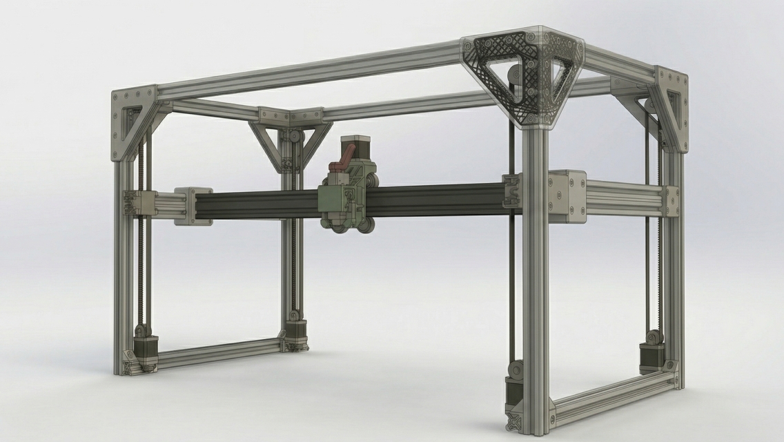
The M3-2 is the default variant of M3-CRETE — a cartesian gantry purpose-built for extruding cementitious materials. Build envelope: 2000 × 1000 × 1000 mm inside a frame roughly 2080 × 1080 × 1080 mm. The full meter of Z travel is recovered from 1000 mm Z-posts by using the bottom Y-skid as structural floor (the build surface sits above it, not below), mounting the Z motors high on the posts, and offsetting the printhead to claw back the last few centimeters of headroom. Big enough to print a standard CMU, a landscape retaining-wall section, or a structural column form in a single run.
Seven NEMA23 steppers drive the machine: one X, two Y (anti-racking), four Z (independent belt-driven posts for Klipper Z_TILT_ADJUST self-tramming). A BTT Kraken with eight onboard TMC5160 drivers runs the movement leaving the final motor slot for a printhead. The printhead mounts via 1-inch NPT and targets a featherweight 1.5 kg — deliberately light to enable knock-on efficiencies allowing frame elements and motors to stay small and safe for use in training as well as production.
One Extrusion. One Length. One Bolt Kit.
Every structural member is a C-beam 40×80. Not a mix of 2040 and 2080 V-slot. Not custom cuts. Not a collection of lengths cut to order. One SKU, one bolt kit, one assembly convention. If you want to order the frame, you order this part and nothing else. 2080 could be used for a printer with more exposed mechanics but we opted for an approach that protects operators and equipment.
Length is a shipping decision, not a structural one. The C-beam's stiffness means the frame works at 1000, 1200, or 1500 mm stock with the same bolt patterns and the same assembly. Pick 1000 mm if you want the kit to fit in a standard UPS or FedEx 42-inch parcel box — a builder in Tucson gets the full frame in two ground-parcel boxes, three days at normal carrier rates, no surcharges. Pick 1200 or 1500 mm if you have pallet handling and want fewer splice joints on the X-axis. The design auto-scales the splice count to the stock length. Every design decision on an open-hardware kit has a shipping manifest attached to it, and the reference build uses 1000 mm because that is the length that reaches a maker space instead of a loading dock.
That was a deliberate choice. Earlier revisions of the M3-2 used mixed 2040 and 2080 V-slot with spliced X-rails. It worked, but it fragmented procurement into four SKUs, three lengths, and two splice methods. C-beam solves all of that at once:
- Procurement is trivial. One line item, one quantity. The reference build calls for roughly 16 pieces of 40×80 C-beam, which ships in two standard ground-parcel boxes at 1000 mm stock or one pallet at longer lengths. A spare or two on the order covers a damaged length in transit and a future repair without holding up a build.
- Bending stiffness is better. 40×80 C-beam bends stiffer than either 2040 or 2080 in the critical axes, and the channel itself acts as a stress-relief rib.
- It's ruggeder. Four V-groove faces plus a channel means you can mount hardware anywhere without planning ahead. Drag chains, limit switches, cable clamps — run any electronics in the interior hollow spaces.
- Honest cost and weight penalty. A C-beam is heavier and slightly more expensive than a 2080. For a frame that's already carrying a 1.5 kg printhead plus a cement hose, "slightly heavier" does not matter. Stiffness does.
Three suppliers have been verified to stock the exact profile in 2026. ZYLtech Engineering (Houston, Texas) ships 40×80 C-beam by US domestic ground, in both 1000 mm and 1200 mm stock lengths — notably the only verified US source that carries the 1200 mm option, which cuts the X-axis splice count. MakerStore USA (Atoka, Oklahoma) ships the same profile via UPS Ground in about three days, in 1000 mm and 1500 mm stock lengths. Bulkman3D ships factory-direct from China by DDP sea freight in about a month, with stock lengths from 100 mm to 1500 mm in 50 mm increments. Prices, lead times, and landed costs will change — builders should check all three before ordering, and if a cheaper or faster source appears tomorrow, the build sheet accommodates it because 40×80 C-beam is a common, widely-stocked SKU, not a proprietary part. The open-source principle applies to sourcing as much as it does to the CAD: the design should not lock you into one vendor.
Against the old mixed-V-slot revision, the story is the same regardless of supplier. Frame weight lands at roughly 27 kg, about seven kilograms heavier than the mixed design. All of that weight sits on the stationary structure, so it has zero impact on print dynamics — it only affects shipping and solo assembly. In exchange the build gets a single-SKU procurement sheet, a measurably stiffer frame, and a parts list a first-time builder can actually follow. That is the trade, and it is the right one.
One caveat up front: the 2000 mm X-axis span still requires splicing at center, regardless of stock length — two equal-length pieces bolted through an internal cube connector, the same method the old V-slot design used. The win is uniformity, not the elimination of splices.
The Design Scope
Frame: roughly 16 C-beam members, stock length chosen to match the builder's shipping path (1000, 1200, or 1500 mm all work) — four vertical Z-posts at the corners, top and bottom Y-rails running front and back, two mid-height Y-gantry rails the gantry carriage rides on, a top X-frame assembly with spliced rails and a center spreader, and the spliced X-axis gantry beam that the printhead carriage rides on. A spare piece or two ships on the order. The parametric CAD auto-adjusts the splice count when the stock length changes.
Motion: seven motors, four generic NEMA23 motor brackets, GT2 10 mm belts, hub disks for the Z-axis, smooth idlers at the bottom of each Z-post, polycarbonate V-wheels with eccentric spacers for zero-backlash adjustment.
Gantry: six plates total — four Z-corner plates, one per post, and two X-carriage plates for the printhead. The old design used sandwich pairs at every corner (eight plates) plus dedicated Y-gantry carriers (two more). C-beam made both of those obsolete. The channel captures the wheels on one face, so a single plate per corner now does the work two used to. The Y-gantry mounts directly to its C-beam rails — no separate carrier plate at all.
Cable management: three drag chain assemblies, one per axis.
Electronics: a BTT Kraken with 8× TMC5160 drivers, a Raspberry Pi 5 running Klipper, a 7-inch touchscreen.
Pump system: intentionally excluded. M3-CRETE is the motion platform. The pump is a separate problem with separate constraints. We will address it separately.
Why CERN-OHL-W
The Weakly Reciprocal variant of CERN's Open Hardware License means: you can use this design commercially, you can modify it, you can integrate it into a larger proprietary system — but if you distribute modified versions of the M3-CRETE hardware itself, those modifications stay open. This is the hardware equivalent of LGPL. It protects the commons without restricting adoption.
The CAD source, BOM, assembly scripts, and component library are all in the GitHub repo. The STEP files are there for people who want to import and build. The Python source is there for people who want to modify, extend, or learn.
How It Was Built
The assembly is a hybrid. A Fusion 360 edit pass handles the parts a human places best — component-library STEPs, fasteners, the visual details. A CadQuery filter-and-replace script loads the Fusion export, classifies parts by bounding-box signature, and surgically replaces the frame members with parametric C-beam templates built from a single stock STEP. Generic NEMA23 motor brackets replace the component-library brackets so nothing in the public repo carries a supplier's IP.
The result is one STEP file you can open in any BREP tool, backed by Python source you can modify in a text editor. A self-verification harness checks engineering invariants against every build — frame dimensions, plate positions, wheel alignments, beam span, clearance gaps — and fails loudly if any of them drift. Regressions get caught before anyone opens Fusion.
Build Log #2 covers this workflow — the hybrid Fusion-plus-CadQuery pattern, the invariant harness, and the AI-assisted development loop — in detail.
Get the Files
- Full STEP assembly:
CAD/M3-2_Assembly.step— 32 MB - Parametric source:
CAD/m3_2_assembly.py - Invariant harness (preview — deep dive in Log #2):
CAD/preview_assembly.py - Interactive BOM: m3-crete.com/bom
- GitHub: github.com/sunnyday-technologies/M3-CRETE
Extrusions on order. Frame build films as soon as they land. Episode 1 of the YouTube build series covers the frame assembly.